Introduction
As the new energy vehicle (NEV) industry expands, the performance, efficiency, and reliability of onboard chargers (OBCs) have become increasingly important. As a key component of electric vehicles (EVs) and plug-in hybrid electric vehicles (PHEVs), an OBC converts AC power from the grid into DC power suitable for charging the vehicle's high-voltage battery. Its performance directly affects charging efficiency, power quality, electrical safety, and overall vehicle reliability.
To meet increasingly demanding testing requirements, manufacturers and laboratories are adopting the regenerative AC source & load for comprehensive OBC testing. These systems can simulate different grid conditions, reproduce abnormal power supply scenarios, and recover electrical energy during testing, helping improve test efficiency while reducing energy consumption.
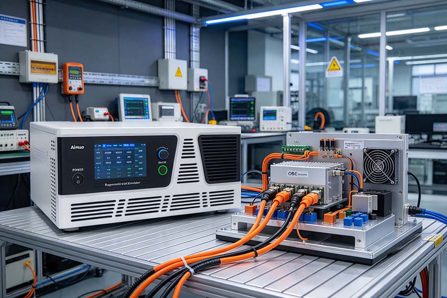
So, what performance parameters of new energy vehicle OBCs can be tested using a regenerative AC source and load? This article explores the major test items, their significance, and how regenerative test equipment supports OBC development and validation.
1. What Is an Onboard Charger (OBC)?
An onboard charger is an essential power conversion device installed inside an electric vehicle. It receives AC power from an external charging source and converts it into regulated DC power to charge the vehicle's traction battery.
Depending on the vehicle architecture, an OBC may support single-phase or three-phase AC input, different input voltage and frequency ranges, and various charging power levels. Modern OBCs may also incorporate power factor correction (PFC), galvanic isolation, communication interfaces, and advanced thermal management.
Because the OBC operates under different electrical and environmental conditions, comprehensive testing is necessary to verify its performance throughout the product development and production process.
Typical OBC validation requirements include:
- Input voltage and frequency adaptability
- AC-to-DC conversion efficiency
- Power factor and harmonic distortion
- Output voltage and current regulation
- Dynamic response and transient performance
- Protection functions and operational stability
- Thermal performance and long-duration reliability
A regenerative AC source and load provides a flexible platform for evaluating many of these characteristics.
2. What Is a Regenerative AC Source and Load?
A regenerative AC source and load is a programmable power testing system designed to supply electrical power to a device under test (DUT), simulate specified AC operating conditions, and, in regenerative configurations, return eligible test energy to the electrical grid or another supported energy bus.
In OBC testing, the AC source simulates the utility grid connected to the charger's input. The regenerative load function can support suitable bidirectional power-flow tests or absorb power from compatible test configurations and return it to the supply network.
The exact capabilities depend on the system architecture. A regenerative AC source, a regenerative AC electronic load, and a bidirectional AC power system are related but distinct solutions. Not every system can perform all three functions independently.
Compared with conventional test setups that dissipate electrical energy as heat, regenerative systems can significantly reduce energy waste during suitable high-power tests.
Key advantages include:
- Programmable AC output: Adjust voltage, frequency, and phase conditions to evaluate OBC operation.
- Abnormal grid simulation: Reproduce selected voltage and frequency disturbances.
- Regenerative energy recovery: Return eligible power to the grid instead of dissipating it as heat.
- Automated testing: Integrate programmable test sequences, measurements, and pass/fail criteria.
- Improved laboratory efficiency: Reduce heat generation and energy costs in appropriate test configurations.
These features make regenerative AC test systems valuable tools for OBC design verification, performance characterization, and production testing.
3. Key OBC Performance Tests Using a Regenerative AC Source and Load
3.1 Input Voltage and Frequency Range Testing
An OBC must operate reliably across its specified AC input voltage and frequency range. Different markets and charging environments may impose different electrical supply requirements.
A programmable regenerative AC source can provide adjustable AC voltage and frequency to verify whether the OBC starts, charges, and operates stably under specified conditions.
Typical test items include:
- Minimum and maximum rated input voltage
- Input voltage variation within the specified operating range
- Rated input frequency and supported frequency limits
- Single-phase or three-phase operation, where applicable
- Startup and shutdown behavior at different input conditions
- Output stability during controlled input changes
By varying the AC input systematically, engineers can identify operating limits, unexpected shutdowns, and performance degradation before the OBC is integrated into a vehicle.
3.2 AC-to-DC Conversion Efficiency
Conversion efficiency is one of the most important OBC performance indicators. It describes how effectively the charger converts input electrical power into useful DC output power.
The basic efficiency calculation is:
Conversion efficiency = DC output power / AC input active power × 100%
For accurate measurement, input and output power should be measured simultaneously under stable operating conditions. Measurement uncertainty, auxiliary power consumption, and the defined test boundary should also be considered.
Efficiency testing typically covers:
- Low-load efficiency
- Medium-load efficiency
- Rated-load efficiency
- Efficiency across the specified input voltage range
- Efficiency at different input frequencies, where relevant
- Efficiency under different output voltage and current conditions
A regenerative test system can help reduce energy consumption during repeated high-power tests. However, accurate efficiency measurement still requires suitable power analyzers, calibrated instrumentation, and a clearly defined measurement method.
Mapping efficiency across the OBC operating range helps engineers identify conversion losses and optimize power semiconductor selection, switching strategies, magnetic components, and thermal design.
3.3 Power Factor Testing
Power factor (PF) indicates how effectively an electrical load uses the supplied AC power. For an OBC, a high power factor generally indicates that input current is well aligned with the input voltage and that reactive and distortion-related power demands are controlled.
A regenerative AC source can supply the OBC with controlled voltage and frequency conditions while a suitable power analyzer measures input power factor.
Important test conditions include:
- Different OBC output power levels
- Minimum and maximum specified input voltages
- Different input frequencies
- Startup and steady-state operation
- Operating points near the rated power limit
Power factor should be evaluated against the applicable product specification or regulatory requirement. Because power factor can vary with load, testing only at rated power may not provide a complete picture of performance.
3.4 Input Current Harmonic Distortion
OBCs use power electronics that can introduce harmonic components into the AC input current. Excessive harmonics may affect power quality and cause electromagnetic interference or additional losses in the electrical supply system.
Total harmonic distortion of input current (THDi) is a common measurement used to characterize harmonic content.
A typical expression is:
THDi = RMS value of harmonic current components / RMS value of the fundamental current × 100%
The exact calculation convention and harmonic range should follow the applicable measurement standard.
Testing can evaluate:
- Input current harmonic spectrum
- THDi at different load levels
- Harmonic performance under different input voltages
- Changes in harmonic content during load transitions
- Compliance with applicable harmonic emission limits
The regenerative AC source establishes controlled input conditions, while a power quality analyzer or power analyzer measures the resulting current waveform and harmonic spectrum.
This information helps engineers assess PFC performance and determine whether circuit or control improvements are needed.
3.5 Output Voltage and Current Regulation
The OBC must deliver the DC output voltage and current requested by the battery charging system or commanded by the relevant charging control interface.
Output regulation testing evaluates whether the charger maintains the required electrical output under varying operating conditions.
Typical test items include:
- Output voltage accuracy
- Output current accuracy
- Output voltage regulation across the specified input range
- Output current regulation
- Performance at minimum and maximum rated output
- Stability during changes in charging commands
- Behavior near specified operating limits
A regenerative AC source supplies the input power, while a suitable DC electronic load, battery simulator, or compatible charging test system establishes the required output operating point.
The testing configuration must be selected according to the OBC topology and the direction of power flow. An AC source alone does not replace the DC-side equipment needed to evaluate output regulation.
3.6 Dynamic Response and Transient Performance
During actual vehicle charging, the OBC may encounter changes in charging commands, input conditions, and battery-side requirements. Its control system must respond without unacceptable overshoot, undershoot, instability, or interruption.
Dynamic testing may include:
- AC input voltage step changes
- Controlled input frequency changes
- Output current command changes
- Output voltage command changes, where supported
- Load step-up and step-down tests
- Startup and shutdown transients
- Recovery following specified input disturbances
Measurements may include response time, settling time, voltage overshoot, current overshoot, and recovery behavior.
A programmable AC source can generate repeatable input disturbances. The DC-side load or battery simulator generates output-side changes, while synchronized measurement equipment records the OBC response.
These tests help verify control-loop stability and ensure that the charger can maintain reliable operation during changing electrical conditions.
3.7 Grid Disturbance and Abnormal Input Testing
An OBC may be exposed to grid disturbances such as voltage dips, voltage swells, frequency deviations, or brief interruptions. Its response must match the applicable product requirements and intended operating behavior.
A programmable AC source can reproduce selected abnormal input conditions in a controlled laboratory environment.
Potential test items include:
- AC voltage dips and swells
- Short-duration voltage interruptions
- Input frequency deviations
- Recovery after the input returns to normal
- Unexpected shutdown and restart behavior
- Protection activation under defined abnormal conditions
Not every OBC is required to continue charging through every disturbance. Depending on the specification, the expected response may be continued operation, controlled derating, safe shutdown, or recovery after the disturbance ends.
The test plan should therefore define both the stimulus and the required response for each condition.
3.8 Three-Phase Input Balance and Phase-Loss Response
For OBCs with three-phase AC input, phase balance and phase-loss behavior can be important aspects of electrical performance validation.
Where supported by the test equipment and permitted by the product specification, engineers can investigate:
- Balanced three-phase input operation
- Phase-voltage imbalance
- Phase loss or phase interruption
- Input current distribution across phases
- Output stability during phase-related disturbances
- Fault detection and protective shutdown behavior
The source must have suitable independent phase control and the required transient capabilities to perform these tests. A conventional three-phase source that only adjusts all phases together may not support every unbalanced or phase-loss scenario.
These tests are particularly relevant when verifying the robustness of three-phase charging systems and their input protection mechanisms.
3.9 Startup, Shutdown, and Protection Functions
OBC protection mechanisms help prevent damage to the charger, vehicle battery, and connected electrical systems.
A programmable AC source can support controlled test sequences for evaluating startup, shutdown, and recovery behavior. Depending on the test configuration, these may include:
- Input overvoltage and undervoltage response
- Input frequency limit response
- Output overvoltage and overcurrent protection
- Overtemperature protection
- Abnormal startup and shutdown sequences
- Recovery after a fault condition is cleared
Some tests require additional DC-side fault simulation, thermal instrumentation, isolation measurement equipment, or dedicated safety test devices.
Protection testing must follow the manufacturer's test procedures and applicable safety requirements. Faults should be introduced using controlled, rated equipment rather than by improvised short circuits or unsafe wiring changes.
3.10 Long-Duration Operation and Thermal Performance
An OBC may operate at elevated power for extended charging periods. Long-duration testing helps determine whether it can maintain stable output without excessive temperature rise, unexpected derating, or thermal shutdown.
Typical measurements include:
- Input and output power stability
- Conversion efficiency over time
- Component and enclosure temperature
- Cooling system performance
- Output derating under elevated temperature
- Unexpected alarms or shutdowns
- Performance after repeated operating cycles
A regenerative AC test system can reduce the heat generated by the test equipment when energy recovery is supported and correctly configured. This can help reduce the laboratory's cooling burden during repeated high-power tests.
However, energy recovery does not eliminate the heat generated by the OBC itself. Thermal testing still requires appropriate temperature sensors, thermocouples, thermal imaging equipment, or other suitable measurement instruments.
4. How Regenerative AC Test Systems Improve OBC Testing Efficiency
Regenerative technology offers benefits beyond electrical parameter simulation.
4.1 Lower Energy Consumption
During conventional high-power testing, much of the consumed energy may be dissipated as heat. A regenerative system can return eligible energy to the electrical supply, reducing the net energy drawn from the grid.
The actual energy savings depend on the test topology, regeneration efficiency, operating profile, and the proportion of power that can be recovered.
4.2 Reduced Heat Generation
By returning power instead of dissipating it entirely as heat, regenerative equipment can reduce the thermal load inside the laboratory.
This can simplify cooling requirements and improve working conditions, especially when multiple high-power charging systems are tested continuously.
4.3 Better Test Repeatability
Programmable voltage, frequency, phase, and transient settings allow engineers to repeat the same test conditions across multiple OBC samples.
Repeatability is essential for design comparisons, engineering change verification, and manufacturing quality control.
4.4 Automated Test Sequences
When integrated with a test automation platform, a regenerative AC source can execute predefined test sequences, collect measurement data, and compare results against specified acceptance limits.
An automated OBC test sequence may include:
- Establish the initial AC input condition.
- Start the OBC according to the defined procedure.
- Measure input and output electrical parameters.
- Change voltage, frequency, or output load as required.
- Record transient and steady-state performance.
- Evaluate the results against predefined limits.
- Generate a test report.
Automation reduces repetitive manual operations and supports consistent test documentation.
5. What Equipment Is Needed for a Complete OBC Test Setup?
Although a regenerative AC source is central to many OBC input tests, a complete test bench usually includes several complementary devices.
Equipment | Main function |
| Regenerative AC source | Simulates the AC grid and specified input disturbances |
| Power analyzer | Measures input power, power factor, efficiency-related parameters, and harmonics |
| DC electronic load or battery simulator | Establishes output operating points and simulates battery-side conditions |
| Oscilloscope and probes | Captures voltage and current waveforms and transient behavior |
| Temperature measurement system | Monitors thermal performance during sustained operation |
| Insulation and dielectric test equipment | Evaluates insulation-related safety requirements |
| Control and data acquisition system | Automates test sequences and records results |
The final configuration depends on the OBC's rated power, input topology, output voltage range, charging control interface, and required compliance tests.
It is also important to distinguish between an AC source that regenerates energy while supplying a DUT and a bidirectional AC load that returns absorbed power to the grid. These capabilities are not interchangeable in every test setup.
6. Which Standards Should Be Considered for OBC Testing?
OBC validation should be based on the target vehicle market, product design, and applicable regulatory requirements.
Potentially relevant standards and regulations include:
- IEC 61851 series: Electric vehicle conductive charging systems and related charging requirements.
- IEC 61000-3-2 and IEC 61000-3-12: Harmonic current emission limits for equipment within their respective scopes and ratings.
- IEC 61000-3-3 and IEC 61000-3-11: Voltage changes, voltage fluctuations, and flicker requirements within their respective scopes.
- CISPR 25: Radio disturbance characteristics for the protection of receivers used on board vehicles and related equipment.
- ISO 21498 series: Electrical specifications and tests for voltage class B electrical propulsion components, where applicable.
These standards do not all address the same test requirements, and some apply to complete charging systems rather than to an OBC as an isolated component. The applicable edition, scope, equipment classification, and market-specific regulations must be checked before preparing a compliance test plan.
A regenerative AC source supports electrical performance testing, but it does not replace the specialized equipment and procedures needed for every EMC, electrical safety, environmental, or vehicle-level validation test.
7. How to Choose a Regenerative AC Source for OBC Testing
Selecting suitable test equipment requires more than matching the OBC's rated power.
Consider the following factors:
1. Rated power and voltage range
Choose a system that supports the OBC's maximum input power, voltage range, and expected operating current with adequate engineering margin.
2. Single-phase and three-phase capability
Verify that the source supports the input configurations used by the OBC, including the required phase control and wiring arrangements.
3. Voltage and frequency programming
Check the adjustment range, setting resolution, regulation accuracy, and dynamic response required for the intended tests.
4. Transient simulation capability
Confirm that the equipment can reproduce the required voltage dips, swells, interruptions, frequency changes, and phase disturbances.
5. Regenerative power capability
Review the available regeneration power, supported direction of power flow, conversion efficiency, and compatibility with the laboratory electrical installation.
6. Measurement accuracy and synchronization
For accurate efficiency and transient measurements, confirm that the power analyzer and acquisition system offer suitable bandwidth, accuracy, sampling, and synchronization.
7. Automation and data integration
Interfaces such as LAN, USB, or other supported communication interfaces can simplify automated test control and data collection. Verify compatibility with the laboratory's existing test software.
8. Safety and protection
Evaluate input and output protection, emergency-stop arrangements, grounding, interlocks, and the installation requirements for regenerative power returned to the facility grid.
A well-matched test system can support OBC development, design verification, and production validation while improving test repeatability and energy efficiency.
Conclusion
A regenerative AC source and load can support a broad range of new energy vehicle onboard charger performance tests, including input voltage and frequency adaptability, conversion efficiency, power factor, input current harmonics, output regulation, dynamic response, grid disturbance behavior, three-phase operation, protection functions, and long-duration stability.
The most effective test setup combines programmable AC power simulation with appropriate DC-side equipment, precision power analysis, waveform capture, thermal measurement, and automated test control.
For OBC manufacturers, automotive suppliers, and power electronics laboratories, regenerative test technology offers a practical way to improve test repeatability, reduce energy waste, and accelerate product development.
When selecting a regenerative AC source and load for OBC validation, engineers should prioritize the required electrical ratings, disturbance simulation capabilities, measurement accuracy, regeneration performance, and compatibility with the intended test procedures.



 TEL:+86 532 83995188
 PHONE:+86 177 5322 5039
 E-MAIL:ainuo@ainuo.com
 ADDRESS:No. 134 Zhuzhou Rd, Laoshan District, Qingdao, China